
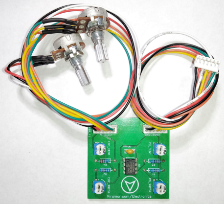
This module will allow you to replace defective Pitch Bend and Mod Wheels on the M-Audio Axiom 25/49/61 V2 keyboards.
It uses standard, easy to find full range 10K Linear potentiometers instead of the almost impossible to find 60 degree Pots used in the original design. The circuit allows you to adjust the range and center positions of the Pots so they work exactly the same as the factory wheels.
It includes two high quality Pots, and if they ever wear out in the future, they are very easy and inexpensive to replace.
If your current Pitch Bend Wheel won’t stay centered, won’t hit the minimum or maximum values, or sends random data even when it’s not moving, and/or your Mod Wheel is behaving erratically, installing this will restore proper functionality.
Installation requires little more effort than installing a used set of Wheels (If you can find any) and these are new… and because the potentiometers are easy to find if they ever wear out again, this will last the lifetime of your keyboard.
No high-tech skills required. It comes fully assembled.
This will ship via USPS (2-5 Business Days), shipping only to United States addresses at this time!

Intro
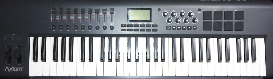
IMPORTANT! This module is only for the M-Audio Axiom V2 keyboard (pictured below).
The V1 keyboard uses a different type of potentiometer for the wheels... the pots included with this kit will not fit the V1.
The images are of the Axiom 61 V2, but these instructions apply to the 25 Key and 49 Key V2, as well.
Installing the module isn't difficult, but remember to take your time. You don't want to break something just before your keyboard is repaired :)
It would be a good idea to read through all of the instructions before you begin to get an overview of what you'll be doing.
Things you'll need:
A Phillips screwdriver (to open the case)
A small pair of pliers (to remove/tighten the potentiometer nuts)
A small flat-head screwdriver (to adjust the trim pots for calibration)
An egg carton or similar container makes a great place to store screws and other pieces as you disassemble the case, and it helps you remember the order they were removed in!
Disassembly
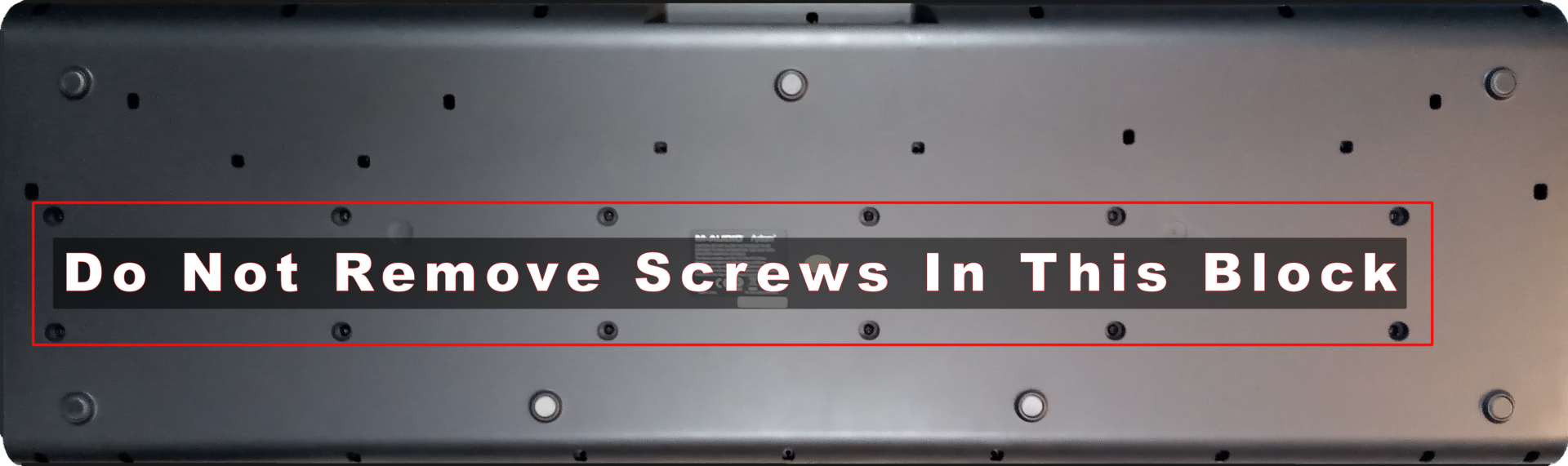
Start by removing all of the screws NOT inside the red block (below). The screws in that block hold the keybed to the bottom of the case... no need to remove that. Keep track of the locations of the screws just above the red block. Most of them are different than the screws around the edges. They have a fine thread because they screw into metal brackets.
Once all the screws are removed, carefully flip the keyboard right side up and remove the top cover by folding it backwards. You may have to move the wiring around a bit to get cover fully open. Don't force anything!
Remove The Wheels
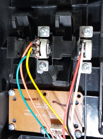
The first thing you want to do is look around and familiarize yourself with location of the wheels and the cable that connects them to the Keyboard's circuit board. Find and remove any cable anchors that are holding the cable in place such as the two right below the wheels. It's a good idea to unscrew the anchors, carefully pull the cable out, and then loosely replace the screw and anchor back in the same place. That way you won't accidentally misplace it and you'll remember where it's supposed to go when you reassemble the keyboard.
Remove the four screws holding the wheel assemblies in place. Look carefully at how each wheel is held in place. Use your fingers to carefully bend the plastic support holding the hub of the Pitch Bend Wheel (on the left). Using your other hand, grasp the metal bracket holding the potentiometer and pull up gently. You should be able to see and feel when the wheel is released from the plastic bracket. Use gentle pressure when bending the plastic bracket back. It's pretty strong, but you don't want to break it! Repeat the process with the Mod Wheel (on the right).
Note that the Pitch Bend Wheel has a spring attached to keep it centered, so when you replace the wheels, the one with the spring will go on the left.
Unplug The Connector
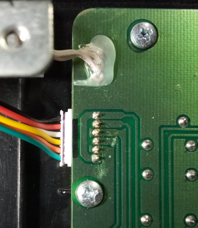
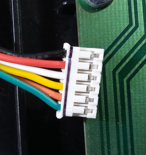
Once the wheels are free and all cable restraints are removed, gently unplug the connector from the circuit board (pictured below). Grab it by the outer edges and rock it back and forth and it will come unplugged. The entire wheel assembly and cables should now be removed.
Remove The Original Pots From The Brackets
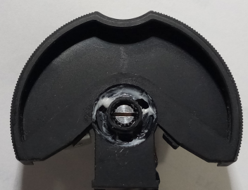
Carefully pull the plastic wheels off of the pots. You can use a screwdriver if necessary, but take your time and make sure you pull it off as straight as possible, otherwise you could damage the plastic wheel.
Pay attention to how the spring is positioned for the Pitch Bend Wheel. It'll help you when you reassemble it.
Once both plastic wheels have been removed, unscrew the nut holding the potentiometer (and the washer) and remove it from the bracket. You can reuse the washers for the new pots (recommended) or use the washers supplied with the new pots, but don't use both... your choice :)
Install The New Pots On The Brackets
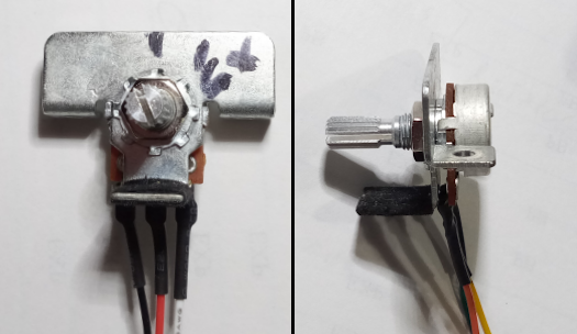
Insert the new pots into the brackets as shown below. You may need to turn the pot body slightly so that the guide pin on the pot is in the correct position. When it's correct, the pot will be perfectly flush with the bracket. Tighten the nuts by hand and snug them up with a pair of pliers. They don't need to be really tight, just snug.
Reinstall The Wheels
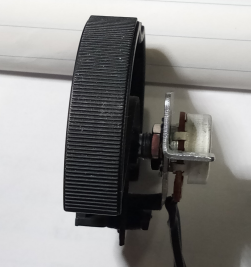
Each pot has a label on the back (PB and EXP). Start with the pot labelled PB. Turn the knob until it's centered. With the wires facing down, the slot should be horizontal. Push the plastic wheel (the one with the spring attached) onto the shaft of the pot until it's almost touching the body of the pot. It should look like the picture below. It should turn freely afterwards. If it's pressed against the body of the pot and is binding, hold the plastic wheel and gently push the shaft back through the pot just enough so the wheel doesn't rub against the pot. Make sure the ends of the spring are on the sides of the felt covered part of the metal bracket. Hold the bracket in one hand and turn it back and forth to make sure it springs back to center.
The slot doesn't need to be perfectly horizontal, the actual center position will be adjusted during calibration... just eyeball it as close as you can ;)
Repeat the process for the Mod Wheel and the pot labelled EXP.
Now that the plastic wheels are on the new pots, you'll need to reinstall them. Start with the Mod Wheel (on the right). Place the plastic wheel in the slot. Carefully pull the plastic bracket to the left while maneuvering the hub of the wheel into its socket. Take your time and be gentle. You don't want to break the plastic bracket. It can be a bit fussy, but once it clicks in, replace the two screws but don't tighten them all the way yet. Make sure the wheel turns freely. If it's binding on the plastic edges of the case, use your fingers or a screwdriver to gently slide the wheel on the potentiometer shaft until the wheel turns without touching. Now tighten the screws and recheck that it turns freely.
Follow the same procedure with the Pitch Bend Wheel.
Plug In The New Connector
Plug the connector (the other wire coming from the module) into the same place the old connector was plugged on the keyboard circuit board. Make sure the side of the connector facing you looks like the picture below. The other side has 2 protruding ridges. Very carefully plug the connector into the main board. It may be difficult to see what you're doing because the circuit board connector is not easily visible. Use a flashlight, put on your glasses if necessary, and take your time. It plugs in easily when aligned properly. Make sure it's all the way in. The edge of the connector should be aligned with the edge of the circuit board. If it's crooked, double check that you've aligned it properly (remove it and start over, if you have to).
It isn't really difficult to plug it in, but it's important that you don't force it if it isn't in the correct position... you could bend the pins. Take your time!
Replace the 2 wire anchors just below the wheels that you removed during disassembly.
Calibrate The Pots
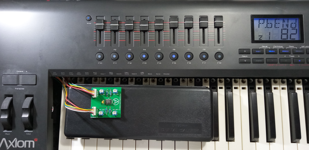
Now for the final step! If possible set up your keyboard similar to the picture below. Set the module board on the keys (with something underneath so the pins won't scratch them up) and gently close the top cover. It doesn't have to be fully closed, you just need to be able to see the keyboard's display while you adjust the module.
You'll need to power up your keyboard for this step. Use the external power supply if you have one or plug in the USB cable from your computer.
Start by wiggling the Pitch Bend Wheel just a bit so that its value is displayed on the keyboard (P.bENd).
Locate the blue and white trim pot on the module board labelled PB_CENT. This is used to center the Pitch Bend Wheel. Using a small screwdriver, carefully (and slowly) turn it until the value displayed on the keyboard is 64. Turning in one direction will raise the value, the other direction lowers it.
You'll notice that there is a "Dead Zone" in the middle where the value will stay at 64 for a while. This is normal. The keyboard uses this to ensure that the center pitch position won't change until the wheel is moved a small amount. You'll want to adjust the wheel so you're as close to the center of this zone as possible. So, when the display reads 64, move the Pitch Bend Wheel up and down slightly so that it moves about the same distance (Up and Down) before the display changes. This doesn't have to be exact, just make sure it feels right to you when you turn the Pitch Bend Wheel.
Once the P.bENd displays 64, locate the blue and white trim pot on the module board labelled PB_WIDTH. This is used to set the overall range of the wheel. Move the Pitch Bend Wheel all the way up (and hold it there) then turn the trim pot (carefully and slowly) until the display shows 127. Turn the Pitch Bend Wheel all the way down and the display should show 0. Repeat moving the Pitch Bend Wheel up and down and adjusting the PB_WIDTH trim pot as necessary until it hits 0 and 127 at the appropriate positions.
You will probably want it to hit these limits just before the wheel is at its physical limits. In other words, adjust it so you can still move the wheel up a tiny bit after it hits 127 and down a tiny bit after it hits 0.
Now the Pitch Bend Wheel should be fully calibrated... 64 when centered, 127 when fully up and 0 when fully down. If everything looks good, move on to the Mod Wheel.
To start, visually center the Mod Wheel by moving it to the same position as the Pitch Bend Wheel (as in the picture below). By default, the display will show cc1. Locate the blue and white trim pot on the module board labelled EXP_CENT. This is used to center the Mod Wheel.
Carefully (and slowly) turn it until the value displayed on the keyboard is 64. There is no "Dead Zone" for the Mod Wheel, so once you get 64, you're good. Now locate the blue and white trim pot on the module board labelled EXP_WIDTH. Move the Mod Wheel all the way to the top and adjust the trim pot so the display shows 127. Move it to the bottom and adjust if necessary until the display shows 0. Repeat the same procedure as the Pitch Bend Wheel to make sure there is a little movement in the wheel at the top and bottom extremes.
That's it! Move both of the wheels to verify they work correctly and you're done with calibration.
Reassemble
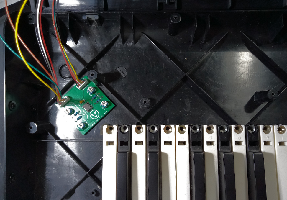
Use the included nylon wire ties to tidy up any loose wires and place the module board in a convenient place like the picture below. Peel the liner from the double-sided tape strip and secure the board to the bottom of the case. You don't need to use a lot of pressure to affix the module board to the case, press just hard enough to stick it in place.
Close the top cover. It's best to start at the back, make sure it's aligned and then carefully lower it.
It would be a very good idea to double check both wheels at this point to make sure nothing came loose up until now. You don't want to replace all those screws on the bottom and then realize you have to open it up again :(
Flip it back over (gently) and begin the long process of replacing the screws. Technically, you don't have to replace all of them... but you didn't hear that from me :)
Final Test
All that's left is to power it up and test it out. It should work as good as new... the wheels, at least!
Problems and Support
If you have any problems or questions, feel free to join the forum here or send an email to